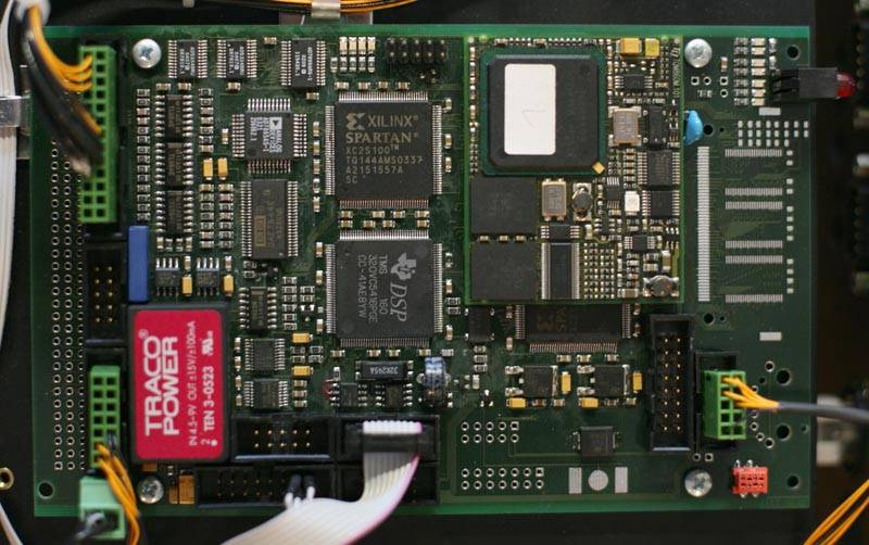
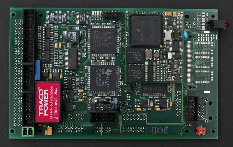
ScanMaster3 - Board Revision 1
Laser projector control board, successor of the award-winning ScanMaster2. The board is an
easy-to-use embedded system for controlling an entire laser projection system. It lets client
computers stream data with standard ethernet and TCP/IP instead of using analog signals
with bulky and lossy cable connections. The use of standard computer interfaces further
eliminates the need for special hardware to be used with the signal source. For standalone
operation, the board offers media playback from memory and user interaction through input
devices connected to DMX512, MIDI or application specific interfaces.
The board can be mounted directly into the projector, be run in a standalone adapter box or be
used in recording and playback systems. Project specific hardware and software can be added
easily for applications with special features such as recorders, measurement systems or
industrially used projectors.

The board comes with outputs and inputs for positioning and monitoring of up to 4
galvanometer scanners, outputs for 8 color channels, power monitoring and device failure
monitoring. For projection system control a fully implemented RS232 port, an I2C bus and
various user I/O signals have been provided. Two dedicated RS232 ports can be used for
user console dialog (same dialog can be held with telnet) and diagnostic messages.
ScanMaster3 can run user software. The firmware bundle is a zip archive containing
software for the base system and the standard ScanMaster3 features. A fully working
default system. Additional firmware, drivers, code for projector feature support like
temperature or voltage monitoring as well as user application code can be added to the
archive and be run by the system. This eliminates the need for further CPUs in the
projection system.
The system supports StageNet's SDCP/SMXP protocols over ethernet and TCP, UDP, IP. See
StageNet.org for more information. All ScanMaster3 interfaces can be accessed with the
protocols and any client can open sessions and exchange data with the unit. For
management a reliable TCP stream is used, for realtime data either UDP or TCP can be used.
Supplemental software features are available separately, as part of a projector support package or
as part of the contractor support program.
System Features
Analog galvo and color ports for up to 4 galvos and up to 8 color lines based on a single
timebase. Applications include satellites and stereoscopic projection.
Capable of managing multiple output windows on each scanhead. Every window can
receive its own data and frame rate. Multiple clients can connect to the unit and
exchange data with their windows. The scanhead output is synchronized transparenty.
Realtime interpolation of curves and vectors. This includes color morphing (different
start and end colors for lines) and soft blanking (either start or end color is black).
Support of multiple color spaces and color transformations.
Geometry processor with corrections for pincushion, linearity and trapezoid.
Transformation of X/Y or X/Y/Z for satellites and 3D used with 4 galvos.
Laser power linearisation, individually for all color lines. Uses an interpolated 8 Bit to
10 Bit map to adjust non-linear laser power response of solid state lasers.
Supports timeshifts for galvo monitor (based on galvo command), color and blanking
(based on galvo command, known as colorshift) and power monitor (based on blanking).
Timeshifts between signal outputs are parameterized in units of microseconds with a
resolution of 1 microsecond. This keeps the configured shift stable for all sample
frequencies.
Operation parameter exchange. This system interface lets clients modify configuration,
view status information and execute remote procedure calls through various protocols
including console dialog, StageNet.org and http.
An external failure input signal controls all safety relevant precautions. It is used for
immediate revocation of visibility (shutter), revocation of validity (digital blanking) and
suppression of color commands.
Safe hardware and software implementation with validity checks and monitoring to
avoid erratic behaviour. Output deactivation in case of malfunction.
Optional Features
Builtin http server for configuration using web-browsers.
Filesystem for CF-Cards (FAT16), read and write support.
Recording of analog laser shows from existing systems.
Monitoring and analysis of galvo command and feedback signals.
Hardware Features: PowerPC Subsystem
10/100MBit twisted pair ethernet with autonegotiation and 7 LEDs for detailed link
status display. Choice of using an onboard RJ45 socket or header for internal wiring.
RS232 console dialog interface and telnet daemon for setup and configuration dialogs
with standard terminal software and telnet clients. Additional RS232 interface for
diagnostic messages.
Fully implemented asynchronous serial port for use with other external devices
including modems or lasers. Alternatively all signals can be used as GPIOs. Level
converters must be attached externally in case the port is used as an RS232 interface.
I2C System expansion bus for communication inside the projector. Intended for PIO
circuits, configuration memory, voltage measurements, temperature control and such.
IrDA port. Physical layer must be attached externally.
2 CAN ports including physical layer.
FPGA for I/O and interface protocol assistance. Provides 42 signals to be used as GPIOs
or with protocols, including a dedicated port for LCD-Display communication.
DMX512 inout and output implemented in the FPGA. Buffered frame and fifo stream
mode available for transmission, fifo stream mode available for reception. Precise
timing and flexible break handling.
Up to 10 partially interrupt capable PowerPC GPIO signals.
8 KByte serial EEPROM for system configuration.
Low power clock circuitry with capacitor and battery backup. The capacitor can keep
the RTC running for about two weeks. The battery will be used thereafter.
CompactFlash Port for use with CF Type I and Type II cards.
Diagnostic LEDs for run status, exception and error code.
133 MHz system clock, 256 MByte SDRAM and 32 MByte flash ROM system memory.
Hardware Features: DSP Subsystem
1x16 Bit quad DAC for (X1, Y1, X2, Y2) commands.
1x14 Bit quad ADC for (X1, Y1, X2, Y2) position feedback.
2x10 Bit quad DAC for color lines, brush, intensity and such.
1x14 Bit ADC for beampower measurements.
Fully implemented ISP output (An adapter board, piggyback or DB25-PCB, must be
used for balancing and isolation).
Fully implemented ISP input (a piggyback adapter board must be used for isolation
and sampling). The input can be used for easier migration of existing analog systems or
recording applications.
FPGA for timing, routing and converter protocol assistence. Provides 16 signals to be
used for synchronisation and serial high-speed links.
Powerful 160 MHz DSP with 256 KByte of 0-wait high speed RAM.
Hardware Features: Board
3-CPU system with a total processing power of approx. 470 MIPS.
High-speed parallel data link between processor subsystems.
Jumper free and fanless operation.
Single +5V power supply.
Clean and stabilized power supplies for all analog circuitry.
100x160mm form factor, 4 layer board, single side mounted, height: 20mm (4HP).
The ease of use, the scalability through networking, its rich feature set and versatility, its
numerous interfaces, its powerful vector engine, local optimizations and monitoring, the
ability to run application specific software, its large computing power while being fanless
and its small size make this board unique in the whole laser industry.
Unlike most other systems ScanMaster3 does point calulation on the fly. Frames arriving from
the network are transformed according to the settings of their associated window and
color space conversion is done. Ordinary point data is passed through the pipeline while
interpolation runs over lines and curves and calculates color morphing and line styles with
the galvo's maximum step increment.
For vector data an optimizer takes care of sharp edges and maximum galvo velocity through
variable timing calculation amd vertex resampling. The rest of the pipeline is power
processing, savety zone control, geometry correction, power linearisation, time shifts, galvo
command output and galvo safety monitoring.
The ability to process the rendering of lines and curves in realtime puts new freedom into
the hands of show designes. Instead of doing the dot monkey, being able to use convenient
strokes and let ScanMaster do the timing.
|